

Among its range of other business focuses, ZEISS is among the leading providers of quality control (QC) and inspection solutions that support users of additive manufacturing (AM) technologies.
Its products are deployed in automotive, medical technology, aerospace, and beyond, and the company has sought in recent years to support the development of fully digitised workflows that help improve quality, understand causes of failure, and drive sustainable improvements.
This week, TCT has been speaking to Paul Brackman [PB], X-ray Product Manager for ZEISS Research & Quality Solutions USA, about how ZEISS is supporting next-generation quality control and defect inspections within additive manufacturing, what 'good' powder characterisation looks like, and how QC needs to improve as AM continues to mature.
TCT: To start us off, can you provide an overview of ZEISS’ product portfolio, particularly the devices that are implemented alongside additive manufacturing?
PB: ZEISS offers an integrated portfolio of technologies and software for quality assurance across the additive manufacturing (AM) workflow—from feedstock characterisation and process development to dimensional inspection and defect analysis of finished parts. Relevant technologies include scanning electron and optical microscopes, 2D and 3D X-ray systems and X-ray microscopes, coordinate-measuring machines (CMM), structured-light 3D scanners, and surface characterisation systems. The supporting software enables manufacturers to visualise and analyse inspection data, evaluate internal defects and dimensional accuracy, automate repeatable workflows, and correlate findings across different technologies. Together, this portfolio helps connect material properties, process parameters, and final-part performance within a consistent quality framework.
TCT: And how would you describe ZEISS’ overall motivations and objectives?
PB: ZEISS’ objective is to help manufacturers move AM from process development into reliable, scalable production. That requires more than inspecting a finished part — it means generating and connecting quality data across materials, process parameters, internal structures, dimensions, and surfaces. By combining measurement technologies with software and application expertise, we aim to help customers understand why a part performs as it does, establish repeatable processes, and make confident decisions throughout the AM workflow.
TCT: We often consider quality control as something that occurs after a part is made, but how important is it to think about quality control in the design process?
PB: Quality control should be considered at the design stage, not treated solely as a final gate. Design for manufacturability (DFM) is well established, but AM also requires design for inspection: engineers need to determine how critical features, internal geometries, and functional surfaces will be verified before a part reaches production. AM can produce highly complex components, yet a feature that cannot be measured reliably cannot be validated with confidence. Building the inspection strategy into the design process helps teams select appropriate measurement technologies, define accessible datums and inspection points, and identify potential verification challenges early, which can reduce costly redesign and support a more credible path from development to repeatable production.
TCT: And what about even further upstream, such as in powder and material characterisation? How much consideration is required here, and are we seeing enough?
PB: Powder and material characterisation require greater attention because feedstock characteristics can influence powder handling, process stability, and, ultimately, the quality and properties of the finished part. A supplier’s certificate of analysis is an important starting point, but it represents a defined set of measurements and does not necessarily demonstrate suitability for a specific AM process, machine, or application.
Particle size distribution, morphology, chemical composition, and potential contamination should therefore be considered against the requirements and sensitivities of the particular process. Depending on the material and technology, other characteristics such as flowability, density, moisture, or surface condition may also be relevant. Appropriate controls should also consider lot-to-lot variation and, where powder is reused, changes associated with handling and repeated processing.
The objective is not to test every conceivable attribute indiscriminately, but to identify and control the material variables that could materially affect process performance or part quality. As AM moves toward more repeatable and qualified production, this upstream evidence becomes an important component of the overall quality-control and process-qualification strategy.
TCT: What does ‘good’ powder characterisation look like? And what happens downstream when it is done poorly?
PB: Good powder characterisation means understanding the feedstock attributes that matter to the specific material, process, and application—and monitoring them consistently enough to identify meaningful variation. That can include particle size distribution and morphology, chemical composition, contamination, flow behaviour, density, and, where relevant, changes associated with handling or reuse. The goal is to build evidence for how the powder is likely to spread and process, and how those characteristics may influence the resulting microstructure and part performance.
When characterisation is insufficient, the effects can surface downstream in different ways. An unexpected particle size distribution can affect layer formation and melting behaviour, while irregular morphology or poor flowability can contribute to inconsistent recoating. Changes in composition or foreign material may introduce inclusions or other localised features that warrant investigation. None of these relationships should be viewed in isolation, but when powder data is connected with process and inspection results, it becomes much easier to identify the source of variation rather than troubleshoot after a build has failed.
From a measurement perspective, the techniques are complementary. Optical microscopy can support particle size and morphology assessment; scanning electron microscopy can reveal finer surface and microstructural detail and, when paired with microanalysis, provide elemental information that helps investigate composition or contamination. X-ray microscopy can add non-destructive 3D insight, including internal density variations and a larger volumetric view of particle populations. Used together—and matched to the question being asked—these methods give manufacturers a more complete basis for powder acceptance, process development, and ongoing control.
TCT: What is the biggest source of deformation you see in the post-print stage (heat treatment, part removal, etc.), and how does earlier-stage CMM or optical scanning help manufacturers catch it before it becomes a costly rework?
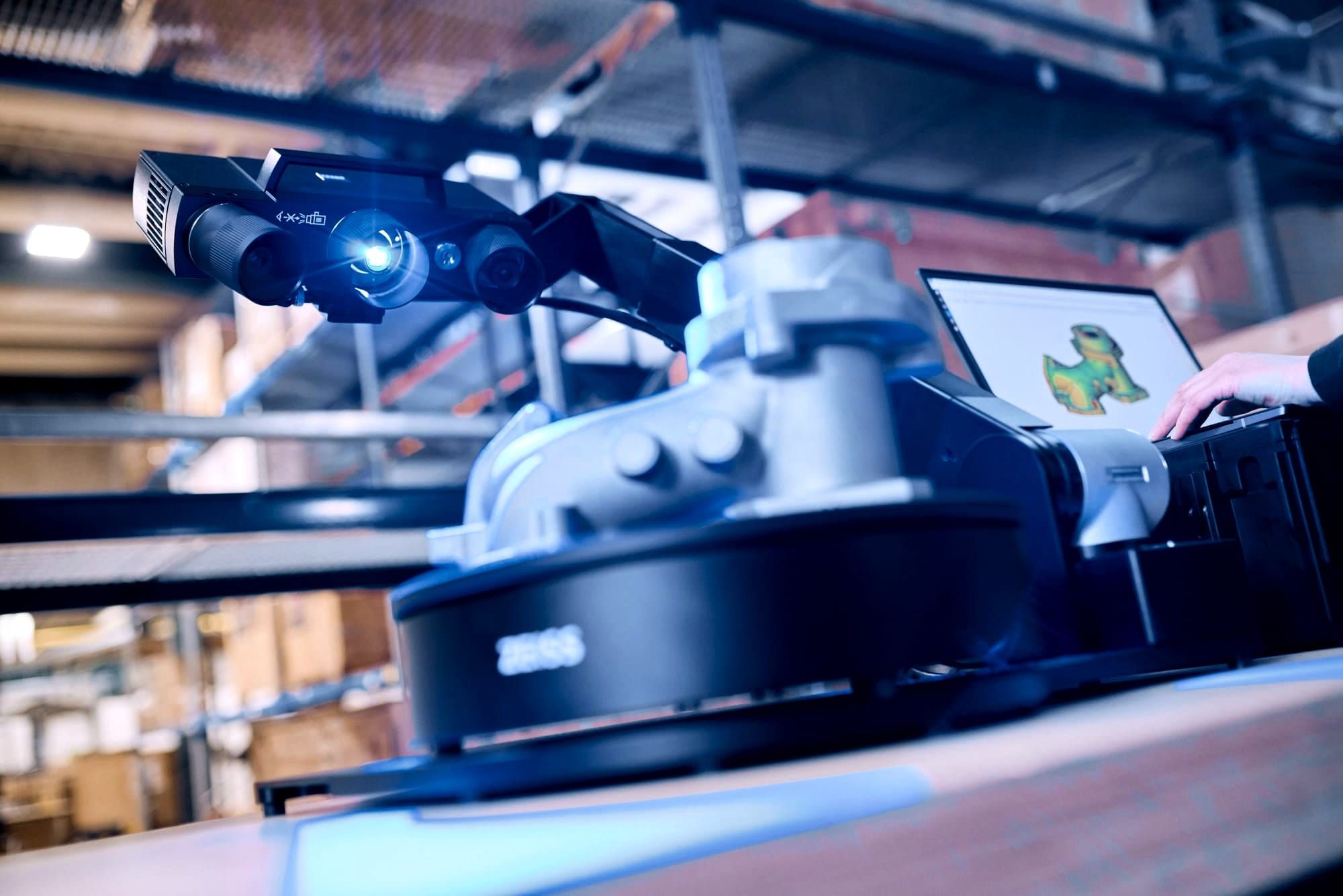
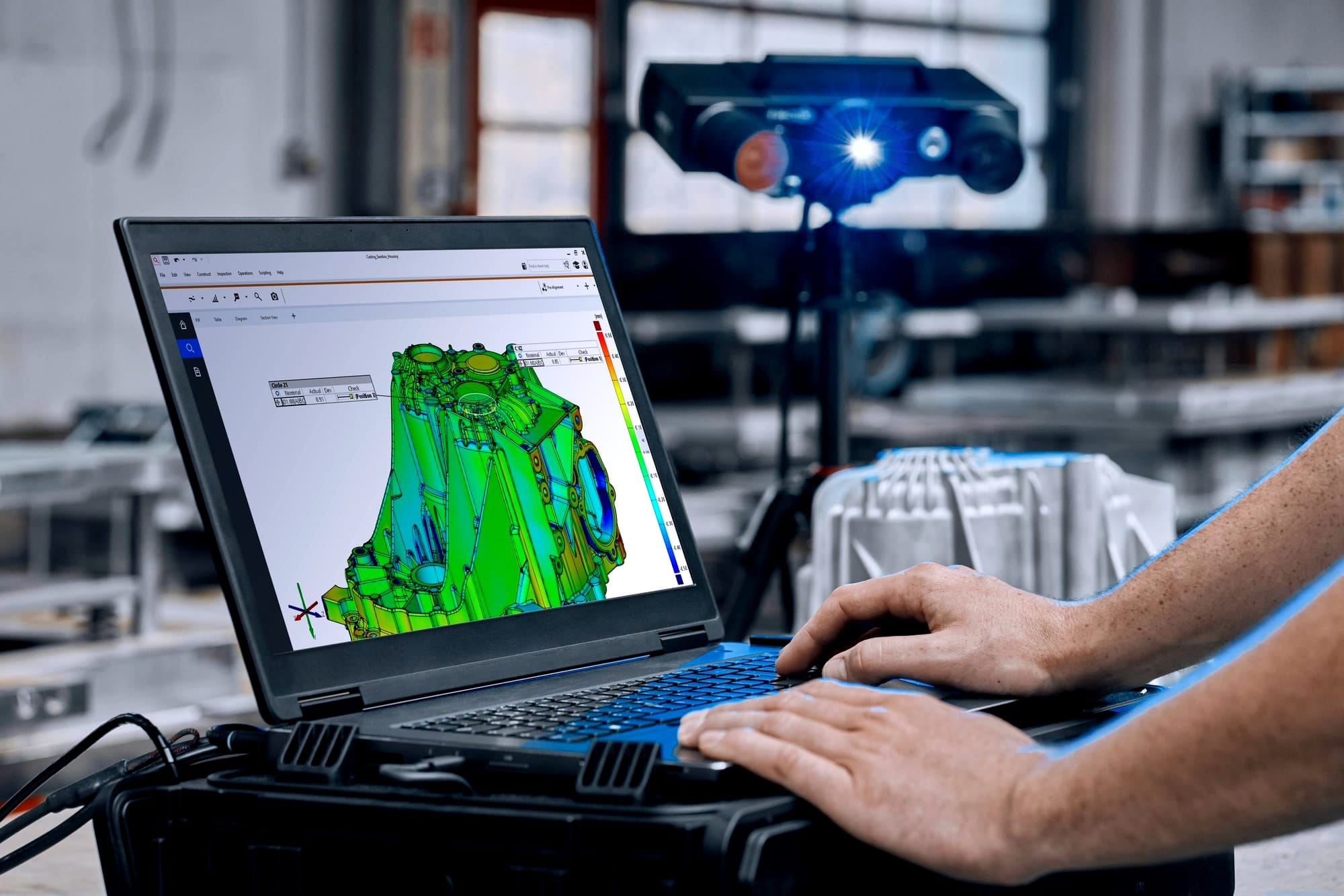
PB: Residual stress is one of the primary contributors to geometric distortion in AM parts, and the geometry can change at several points after printing—including heat treatment, support removal, and separation from the build plate. The right measurement approach depends on the part, its tolerances, and its intended use. ZEISS ATOS 3D scanners can capture full-field 3D measurement data between process steps, making it possible to see where and when deformation occurs rather than relying on a limited set of measurement points. In ZEISS INSPECT, that data can be aligned with the nominal CAD model, visualised as a colour deviation map, and used to evaluate dimensional changes across the complete accessible surface. CMM inspection can complement this analysis where highly accurate verification of defined features, datums, and functional dimensions is required.
Depending on the application, geometry compensation based on 3D scan data can provide a practical route to reducing distortion. The as-built part is captured using 3D scanning, and the resulting scan data is evaluated against the nominal CAD geometry in ZEISS INSPECT to identify and quantify deviations. An inverse compensation can then be applied to the manufacturing geometry before the next build. By repeating the cycle of 3D scanning, deviation analysis in ZEISS INSPECT, and geometry compensation, the process can, after a limited number of iterations, move closer to near-net-shape production, although the outcome depends on the material, geometry, and process stability.
Heat treatment and other post-processing steps add complexity, so parts should be 3D scanned at the relevant stages to quantify how the geometry changes throughout the process and separate the effects of different process steps. Simulation can help predict non-linear shrinkage and warpage, but 3D scan data provides the experimental evidence needed to validate the model, refine the compensation strategy, and determine whether the resulting part meets its geometric requirements.
TCT: X-ray CT scanning is core to much of your defect and internal-structure inspection work. What can CT catch that other inspection methods can’t? And where does it hit its limits?
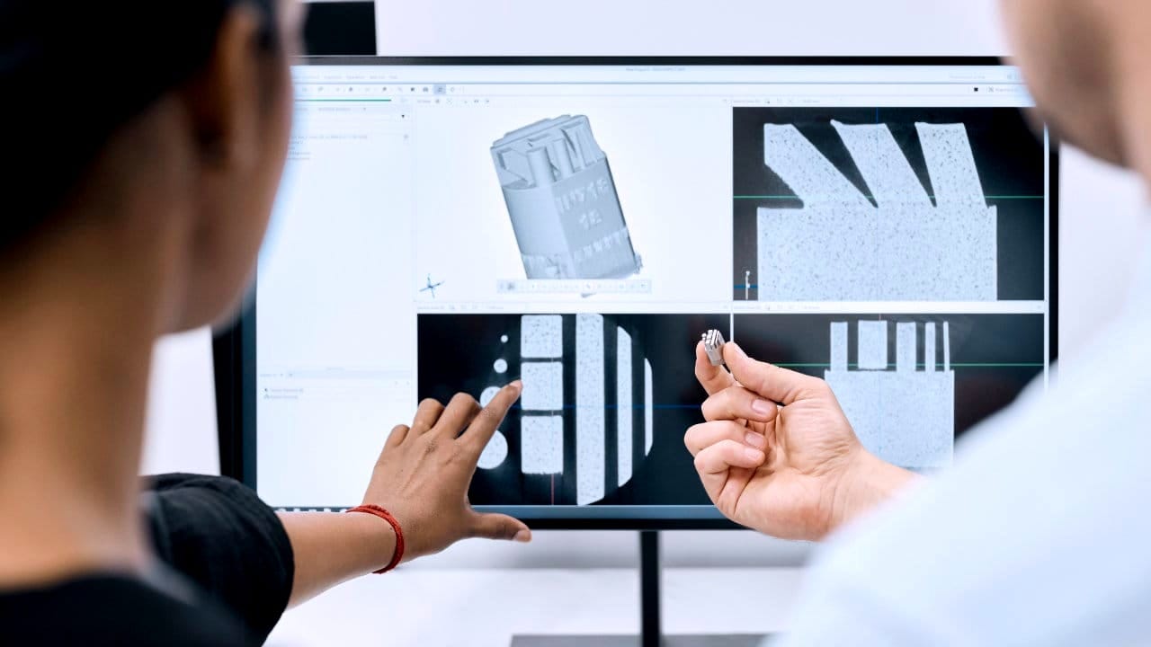
PB: In our AM inspection labs, X-ray CT (XCT) is often the first technology used. The ability to put a part inside the CT scanner without special fixturing and get a 3D representation of the external geometry and internal defect structure within minutes is invaluable. Even if you know the part has cracks or externally visible defects marking it for scrap, XCT can show you where the crack is originating, quantify the amount of deformation, and provide a digital twin of what that part looked like at that exact time. The richness of the data coming from the scanner allows us to find high-density inclusions we didn’t know existed, measure surface roughness of internal features, trace phase changes in materials back to porosity (and reduced fatigue life), qualify 3D printers based on build plate mapping of defects/laser variations, and help our partners with printer equivalency. The limitations are the same they have always been: the X-rays need to be able to penetrate the material to provide a signal. We see a growing use of refractory metals and copper-based 3D printing, and for this reason we have added a new, higher-voltage option to our portfolio of METROTOM metrology-grade industrial CT scanners: the METROTOM 800 320 kV. This high-kV CT scanner was intentionally engineered to solve the challenge of getting high-resolution, high-fidelity images from dense AM parts.
TCT: Can you talk us through ZEISS’ AM VERCES offering? What was the motivation for this product?
PB: ZEISS serves both research and industrial markets, and we recognised that both were asking for something that could be solved by one process: AM VERCES. Research organisations were looking for a way to optimise laser/electron beam parameters when working with new alloys or non-prescribed grades of powder. Industrial customers were looking for a way to map build plates (“If I print at the top right of the plate, do I get the same quality as if I print at the bottom left?”), ensure printer equivalency (“Does my printer SN 1001 print the same quality as SN 1002? What about SN 1003 in the building next door; what about 1004 overseas?”), and track printer health (“How does my print quality look one day after a maintenance visit? One month? Six months? One day before the next visit?”). We prescribe AM VERCES as a qualification routine to anyone who has questions about these topics.
TCT: As manufacturers look to scale with AM, they need confidence in every part and they need throughput. How can these companies strike the right balance between efficiency and efficacy?
PB: We typically group quality-control requirements into two stages: R&D and production. In R&D, the priority is to understand the relationships among the material, process parameters, and resulting part quality. Once manufacturers move into production, the fundamentals are similar to those of other manufacturing methods: first demonstrate that the process is stable and repeatable, then apply the appropriate functional and dimensional checks based on the part requirements and the level of risk. The right inspection strategy will not be the same for every application. It may range from statistically justified batch sampling to 100% inspection, depending on factors such as process maturity, part criticality, and regulatory requirements. ZEISS supports that flexibility with automation and cycle-time improvements—including palletisation, reusable inspection templates, robotic loading and unloading, and automated analysis tools—so manufacturers can scale inspection capacity while maintaining confidence in the results.
TCT: ZEISS works with customers in a range of industries, from medical to aerospace to energy, so how do you serve their varying needs? Are their quality-control demands vastly different, or are there fundamentals that cross over?
PB: The fundamentals are consistent across industries: manufacturers need to understand the material, control the process, and verify that the finished part meets its intended requirements. What changes is the risk profile around the application. A medical implant, an aerospace component, and an energy application may require different evidence, inspection strategies, traceability, and regulatory considerations—even when they use similar AM processes. ZEISS addresses that balance by combining a connected portfolio of measurement technologies and software with dedicated industry expertise. Local segment specialists work with global teams to bring application knowledge and customer feedback into the development of relevant workflows and solutions. That helps us start with the manufacturing challenge and the evidence the customer needs, rather than applying the same inspection approach to every part or industry.
TCT: As AM pushes further into series production, what has to change about quality control to keep pace?
PB: Quality control has to become more integrated, automated, and data-driven as AM moves into series production. Automation is well established across manufacturing, but adoption in the quality lab has often lagged; operators still manually load parts and initiate inspection plans on many systems. ZEISS has a dedicated team developing automated solutions, from robot-loaded coordinate measuring machines and palletised fixtures for microscopy to fully integrated, conveyor-fed inline X-ray systems. As AM production becomes increasingly automated, quality assurance must be connected to that workflow rather than remain a separate downstream step. AI also has significant potential in production quality. ZEISS has used AI-based methods for several years in image processing and analysis of X-ray, optical microscopy, and electron microscopy data. For suitable applications, trained models can accelerate image acquisition and analysis while improving consistency and helping operators evaluate large data volumes. The priority, however, is not automation for its own sake: any AI-enabled workflow must be validated for the application and supported by appropriate standards, traceability, and human oversight. As these tools mature, they can help manufacturers increase inspection throughput without compromising confidence in the result.


