

Ask an engineer for the stiffness of aluminium, and they'll give you one number, whether the alloy is 6061 or 7075, soft or heat-treated. Ask for the stiffness of a 3D-printed part, and the honest answer is: it depends how it was sliced.
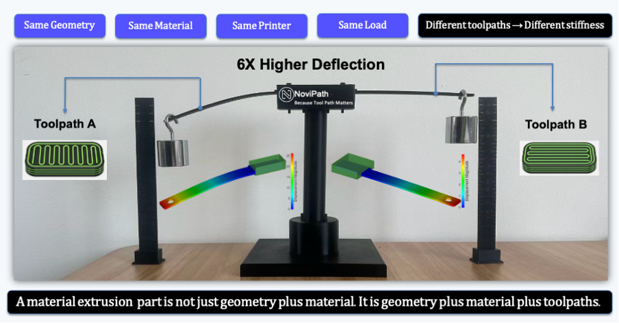
We prove that with two ‘identical’ beams displayed in our offices. The beams are made from the same material, from the same printer, with the same geometry, under the same load. The only difference is the internal toolpath. One beam bends six times more than the other under the same weight (Figure 1). Visitors assume the ‘softer’ one is defective. But it isn’t really, it's just following different instructions. In extrusion-based printing, the process is the material.
That demo is the easy version of a problem we've been chasing for months. As part of an ongoing test campaign with our partner Stratasys, we've been mechanically testing high-performance materials such as Nylon 12CF, Antero 800NA and ULTEM 9085 across multiple printers and toolpath settings, building the data behind NoviPath, our toolpath-aware simulation software. Most of what we found confirmed the physics we expected but there was one surprising result.
Same material, three different answers
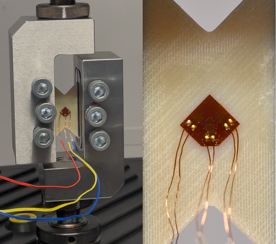
We tested identical shear coupons printed three ways: raster running straight along the load, straight across it, and diagonally at ±45 degrees. Each coupon was instrumented with rosette strain gauges (Figure 2), so we could see exactly how much each construction resisted the shearing load. The straight versions agreed with each other, which is exactly what should happen when you're measuring a material constant.
For Nylon 12CF material, the ±45-degree version measured three and a half times stiffer.
Nothing about the material changed. What changed is that at ±45 degrees, the printer doesn't lay down one direction of filament; it alternates, building a diagonal crisscross that carries load very differently from a straight raster. In the ±45-degree coupons, that crisscross behaves like a pair of crossed diagonal braces: the shear load resolves into tension and compression running along the filaments themselves. In the straight-raster coupons, the same load has to slide across the weaker bond lines between filaments, which is why those two coupons agree with each other and read low. Simulation software needs shear modulus as the input. An engineer who read that ±45-degree number off a test report and treated it as the shear modulus would carry a 250% error into their analysis, with nothing on the sheet to flag it. It wasn't a surprise to us as the underlying physics predicted it, but having it confirmed on real parts mattered.
The result that genuinely surprised us was less obvious.
One pass, 60% more strength
We printed two batches of otherwise identical test coupons: same material, same raster pattern, same everything, oriented the weakest possible way relative to the load. The only difference was a single extra outline traced around the edge of one batch before the infill began, a sliver of plastic worth a few percent of the part's cross-section. It's the kind of detail a slicer can change, and exactly the kind of detail conventional FEA throws away by averaging it out.
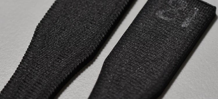
The coupons with that one extra contour were 60% stronger. Nothing in the test standard says anything about it. ASTM D638 was not written for FDM parts. Two labs can follow the same standard and report strengths 60% apart, and both are right. The explanation was hiding in plain sight (Figure 3). Without an outline, the edge of a printed part isn't smooth: it's a row of exposed filament ends, each one a tiny crack waiting to start. Add a single contour pass, and that ragged edge becomes one continuous, unbroken strand of material running the full length of the part. It's both carrying load and erasing the flaw caused by the ‘unsealed’ ends.
One line of plastic mattered: it changed the toolpaths by less than 6% but delivered 60% more strength. It cost us weeks of head-scratching before we worked out why. We're now running a dedicated follow-up study, deliberately varying how many contour passes we add around test features, to learn exactly when that single line stops being a side effect and starts being a design choice.
Why it matters outside the lab
A simulation is only as trustworthy as the material data behind it, and a datasheet number that ignores how a part was sliced can be wrong by a factor of two, three, or more, in either direction, with nothing on the test report to warn you. That becomes a knowable error that separates a part that survives its design load and one that doesn’t.
That's the gap we're closing. By the time this program wraps, we will have run more than 1,500 individual tests across three materials, three printers and multiple toolpath strategies, all cross-checked against simulation. That scale means that instead of testing every new combination of material, printer and design from scratch, the goal is a model that can predict performance for a new combination of material, printer and toolpath from a handful of confirming tests, because the physics already gives most of the answer.
The bigger goal is to get to a 3D-printed part that ships with a trustworthy performance record built from a handful of coupons, not repeated guesswork every time a material, machine or design changes. Right now, qualification is expensive precisely because it doesn't transfer. Every new configuration means starting the physical testing over from scratch. Treat the toolpath as an engineering input on the same footing as geometry and material, something a model consumes rather than something the slicer discards, and that cost stops repeating for every part and starts compounding into something the whole industry can reuse.
These are exactly the kinds of problems that need to be solved to allow additive manufacturing to graduate from making parts to trusted production.
Authored by Novineer CEO Ali Tamijani
Ali Tamijani holds a Ph.D. in Engineering Mechanics from Virginia Tech. For two decades, he has developed computational design and optimisation tools. He founded Novineer in 2022 alongside Director of R&D Zhichao Wang, Ph.D.
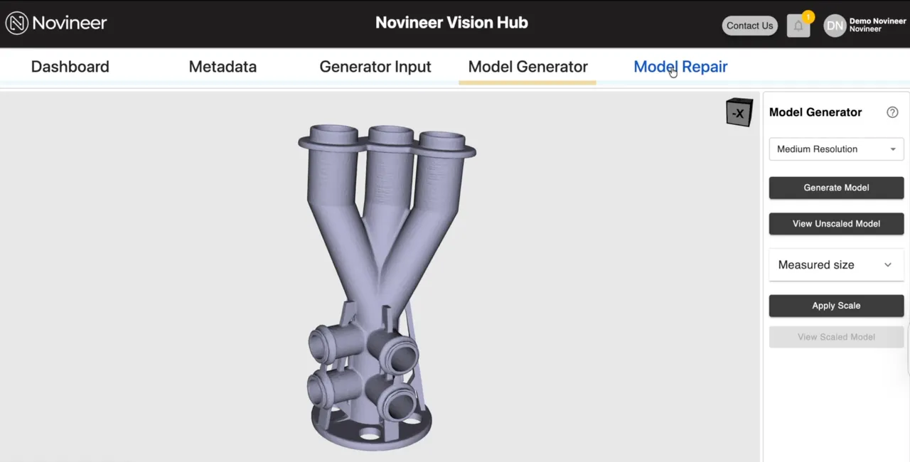
From image to editable CAD in minutes: Novineer introduces NoviVision software tool
Group Content Manager Sam Davies speaks to Novineer CEO Dr Ali Tamijani.


